Crane Design and Use
This page contains a description of the design and use of my crane. The crane evolved over time as I ran into problems, so this description is of the final result. If you are interested in the various dumb ideas and problems I had along the way, click here.
I couldn't use Skip's method of corner lifting poles because of the irregularity and inaccessibility of my building site. I had to do something else so I decided to build a crane. It ended up working very well, so the ideas in these pages might be useful to other people with similar problems.
The General Design
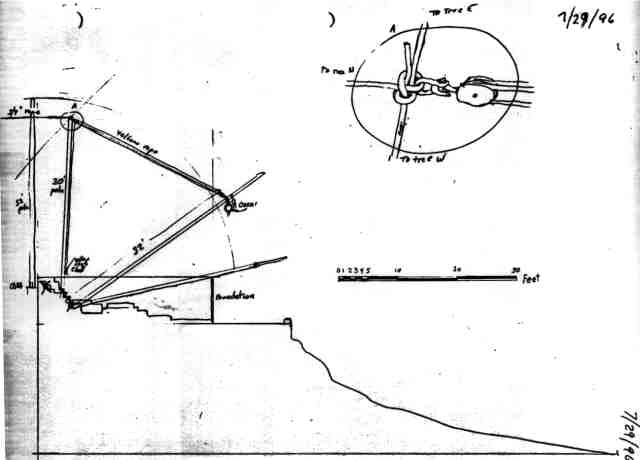
The diagram below is a scale elevation drawing of the site and the foundation. The top of the foundation is the highest horizontal line on the drawing with an 8 foot wall on the right side and an 8 inch wall on the left side. The horizontal line to the right of the foundation (with the curb) is the upper roadway. The logs were in a log pile just off the diagram to the right. I not only had to lift my logs up onto the building, but I had to drag them up that hill. (Ignore the drawing of the knot and block at the upper right for now. That was a dumb idea.)
The parts of the crane are shown on the next diagram.
The mast (M) was a nearly-vertical 32-foot log. The mast was held in position by three 3/4" guy ropes (G1, G2, G3). Initially, the base of the mast simply rested on a ledge in the rock cliff behind the building. As the building grew the mast was moved higher up the cliff. Eventually, the bottom was held fast to the outside of the log wall by a loop of chain.
The boom (B) was a 32-foot log that swivelled about a Crane Boom Abutment (CBA). The end of the boom was attached to a 4-way block and tackle which ran to the top of the mast. This held the end of the boom up. The 5/8" rope from the block and tackle ran down the mast and was held fast by a cleat (C) attached to the mast. The boom could swing from side to side and could be prevented from swinging by snugging and cleating the sheets (S1 and S2). S2 ran through a pulley attached to a tree as shown and from there, through a vent opening in the foundation wall. That way, S2 could be controlled from inside the building. S1 was simply fastened to a tree.
Initially, the CBA was simply a depression in the bedrock. As the building grew, The CBA was a log tripod structure that was bolted to the log wall. The CBA was periodically raised as the building grew. The CBA kept the boom far enough away from the wall so that the boom could be nearly vertical without hitting the scaffolding that was directly above the CBA.
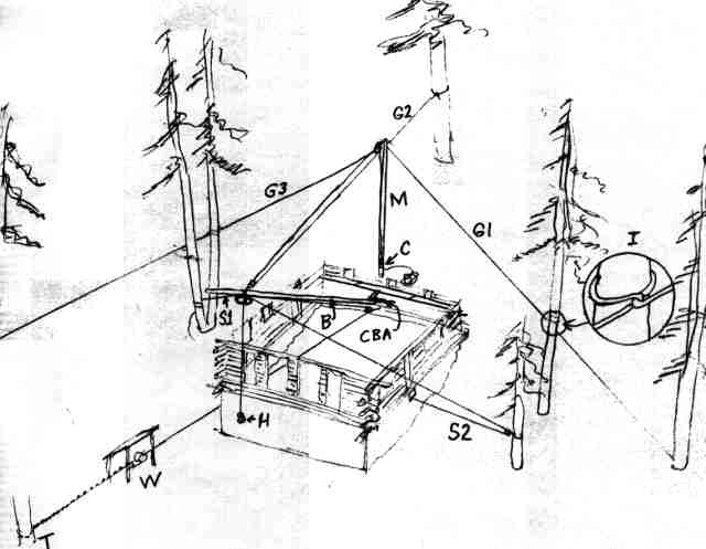
The hook (H) hung from a cable or chain from the same point on the boom that the sheets and the block and tackle were attached. Initially, I used a 1/4-ton electric chain hoist attached directly to the boom. This hoist had a 30-foot chain. When the hoist finally gave up the ghost, I began using an electric winch (W). The winch was chained to a tree (T) and the winch cable then ran through the crawl space door up to a block fastened to the wall below the CBA. From that block, the cable ran up the boom to another block fastened where the chain hoist used to be, and from there, the cable went down to the hook (H).
To keep the boom from tending to swing one way or the other, I kept the top of the mast directly over the swivel in the CBA. To accomplish this, I had a mason's line attached to the top of the mast with a plumb bob hanging at the bottom. That meant that the mast was leaning somewhat toward the front of the building. The plumb bob told me which way, if any, I needed to move the mast to line it up. To adjust the mast alignment, I adjusted the knots holding the guys (G1, G2, G3). As it turned out, the vertical alignment of the mast is not very critical. I hardly ever had to adjust it.
Both G1 and G3 were each attached to two trees. The guy was made fast to the base of the far tree, but a hitch, that I have since named the Martin's Differential Hitch. as shown on the inset (I) was used on the near tree. This allowed some amount of adjustment of the guy without having to climb up the tree.
G2 was always in high tension, and as you can see from the diagram, G2 bore nearly all the weight of every load on the hook. G1 and G3 were typically not in so much tension, and in fact, they were somewhat slack. If the boom were swung to the right in the picture, G3 would bear a component of the force, but G1 would be completely slack. One side benefit of this was that the slack in G1 allowed the boom to swing further to the right than it otherwise could. The same held true for the other direction. This also meant that as the boom moved to the right, for example, the mast would then be aligned to the right of the CBA and the boom would have more of a tendency to swing to the right. This was typically not a problem. It simply meant that I could control the boom's swing with a single sheet, in this case S1.
Design Details
The Mast
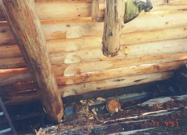
In the next picture, you can see the bottom of the mast with the chain wrapped in a groove at the bottom. The short log with my jacket hanging on it is there to stand the mast off away from the building so it can lean toward the building a little without hitting the log wall. The chain runs up over the short log and then is fastened to the wall with a big eye bolt with a 2x6, washer, and nut on the inside of the building.
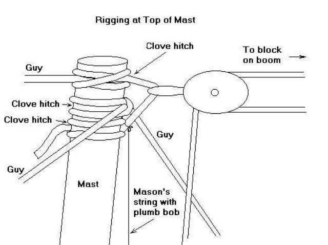
The next drawing shows the rigging at the top of the mast. I used two 3/4" manilla ropes for the guys. G1 and G3 were the same rope fastened to the mast by the middle one of the three clove hitches. G2 was fastened to the mast by the top clove hitch with another clove hitch tied as shown as the bottom one of the three. The block and tackle is hooked to the short length of rope between the top and bottom clove hitches.
I show those two hitches tied on opposite sides of the mast. This was intentional in order to reduce the twisting forces on the mast because each hitch would tend to twist the mast a different direction. But in reality, I think it would be better to tie the hitches on the same side because together, the forces from the block would cancel out the force from G2. It would also make that short length of rope vertical, rather than slant from one side of the mast to another. That would help keep the block in alignment in case there is no swivel on the block. If the hook on the block does not swivel, and if it is 90 degrees off, you can use a shackle to effectively turn it 90 degrees. It is important that the block is oriented so that the pulling rope coming out of it is aimed straight down the mast so the block doesn't bind.
Since it isn't easy to do anything with the top of the mast once it is 30 feet off the ground, all the rigging up there must be in place before you raise the mast. That includes the mason's string with the plumb bob that will allow you to know how the mast is aligned vertically. The diagram shows how I tied it on.
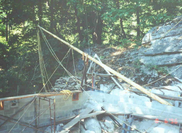
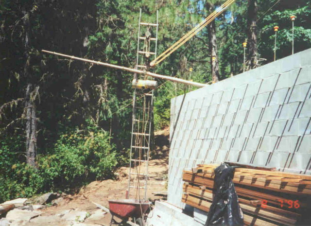
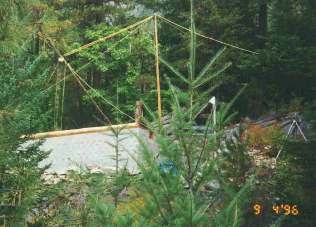
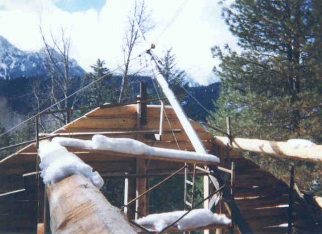
In the next picture, you can see the mast on the way up. You can see the yellow rope in the block and tackle, and you can see two of the guys (G1 and G3) attached to the top. G2 is behind the mast so you can't see it at the top but you can see it draping down to the right and then back up against the High Rock on the right.
To raise the mast, I used a temporary block and tackle attached near the middle of the mast and going high up into a tree off the picture to the right. That temporary block and tackle is not visible in this picture because it was being re-rigged at this point. It took all the rope I had to raise the mast this far, so I propped the mast up with a couple of 4x4s which you can see sticking up just to the left of the corner of the foundation. These 4x4s had short 2x4s bolted on that formed cradles for the mast to rest in. If I remember right, I had enough rope to raise the mast the rest of the way from here with just one rigging.
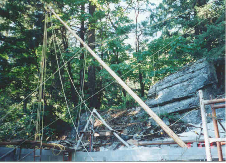
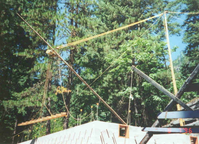
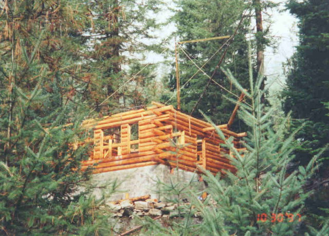
In the next picture, you can see the mast further along on its way up and you can see the temporary block and tackle attached to the middle of it. You can also see two guy ropes attached at that point which allowed me to control where the mast went on its way up. Once it got nearly vertical, the permanent guys, G1, G2, G3, took over the job.
The Boom
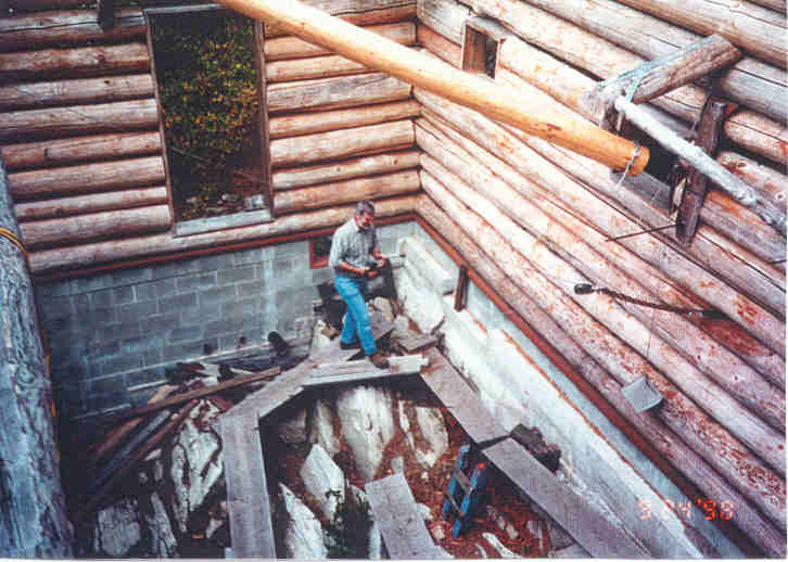
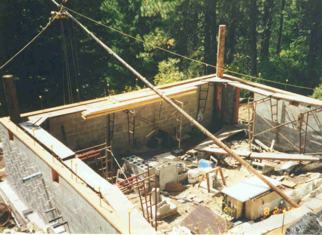
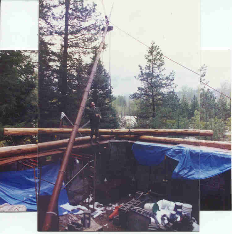
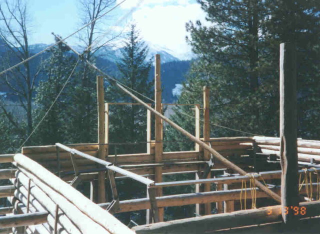
At the upper right in the next picture, you can see the lower part of the boom fastened to the CBA. (That's my brother, John, in the center of the picture.)
You can see some other parts of the crane in this picture. On the right side, you can see the block for the crane hook cable. The block is attached to the wall with a short chain attached between the fifth and sixth log courses. You can see the cable going up to the end of the boom coming out of the block heading for John's head, and you can see it against the open doorway and against a couple logs on the left.
The other end of the cable coming out of the block is harder to see. It heads down in the direction of John's knee and then goes through the door in the foundation (not shown) on its way to the winch.
The small concrete block you see hanging from a rope below the CBA is a counterweight. The rope goes through a pulley under the CBA and then is attached to the chain near the crane hook block. When there is no load on the crane hook, the slack causes the block, chain, and cable to sag down so you hit your head on it when you are walking on the scaffolds like John is here. With the counterweight, the block is pulled up out of the way so you don't hit it. In this picture, it looks like there is a load on the hook so the cable is tight and out of the way. The counterbalance is doing nothing in this case.
You can also see the 2x6 against the wall inside the CBA which is part of the anchor for the chain holding the mast up on the outside of the wall.
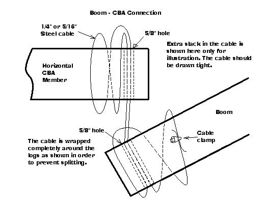
The next drawing shows how the boom is fastened to the CBA with a single length of cable. The reason for the complete wrap of the cable around each log is to prevent splitting.
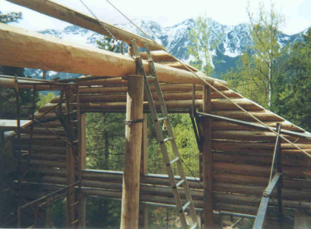
In the final configuration, of using a winch instead of an electric chain hoist, rigging the end of the boom would be no problem. But getting that 90 lb. hoist attached to the end of the boom was a little tricky. The next picture shows how I did it.
With the boom resting on the foundation, the point of attachment was about five feet out from the foundation wall and about 9 feet off the ground. There was nothing but the boom itself to lean a ladder against. So I lashed the boom to one of the rebar sticking up out of the foundation to keep it from moving. Then I attached a block and tackle to the highest rung of the ladder, as you can see in the picture. I used this to lift the hoist up out of a wheelbarrow and up to the boom. The real tricky part was getting the hook on the hoist to go into the big shackle on the boom. I suppose if I could lift 90 pounds with my arms straight out while standing on that ladder, I could have just muscled it into place. But just standing on that ladder with no visible means of support was rickety enough that I didn't want to take any chances.
Instead, I made a six-inch loop of number 9 wire and used it to connect the hook on the hoist to the hook on the block and tackle. Then with the hoist hook hanging beside, and just above the shackle, I hooked a come-along to the wire loop and used it to pull the loop over so the point of the hoist hook started into the shackle. Then by relaxing the block and tackle just a little, and cranking the come-along one notch, and alternating this way, I transferred most of the weight of the hoist to the come-along which placed the hook well inside the shackle. Then I just relaxed the block and tackle, backed the come-along off and lowered the hoist so the hook was in the shackle.
The loop of wire was now stuck around the hook and shackle, but it didn't hurt anything being there so I just left it. That way I could use the reverse process to get the hoist back off when the time came.
Incidentally, I deliberately didn't cut off the excess length of the boom. Instead, I used that spar to hold a 1/4" rope that formed the sling for my gwizard.
Operating the Crane
To operate the crane, I would typically raise or lower the boom to where I wanted it by uncleating the 5/8" rope from the cleat (C) and then pulling in or paying out enough rope to position the boom. Then I would cleat the rope again. I did this adjustment without any load on the hook.
Next I would position the boom horizontally by adjusting the sheets (S1, S2) and fastening the sheets. Finally I would pay out all the chain or cable from the hoist or winch and attach the hook to the load. Typically the load would be either a series of chains and cables going down to a log at the log pile a hundred feet away, or it would be to a choker on a log somewhere on or near the building that I wanted to move to a new position. I would typically have the end of the boom directly above the point where I wanted the center of gravity of the load to end up. If I was manipulating a log, the choker would typically be right at the log's center of gravity.
In the next picture you can see the crane lifting its very first load: just a couple of stair strings. Even though the load was pretty small, I was very excited to have the thing work as imagined. Great fun.
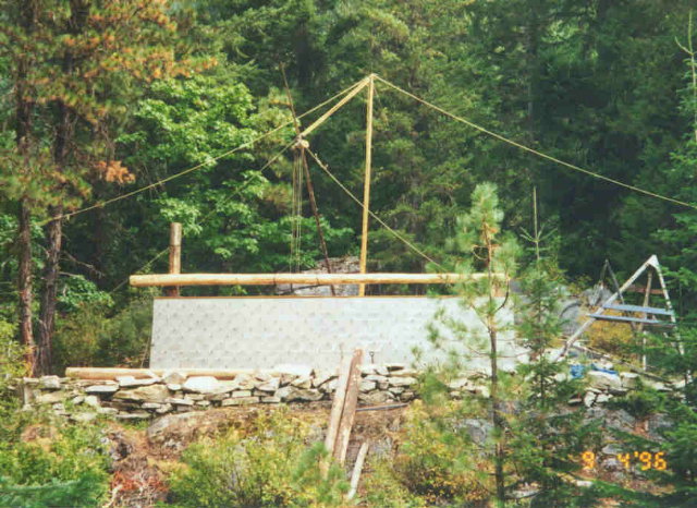
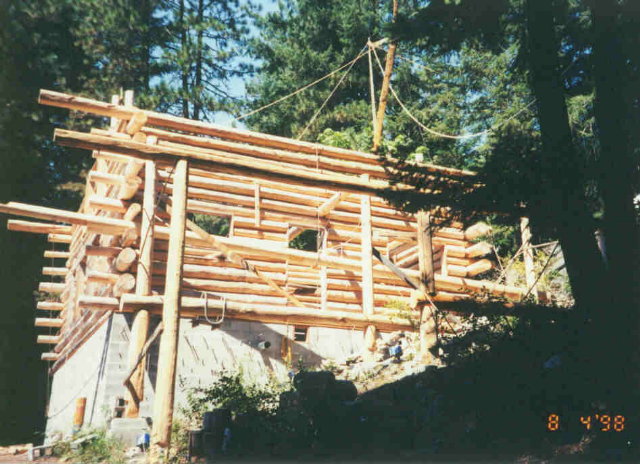
Here you can see pretty much the entire boom.
Here you can see the crane lowering the very first log in the wall. It is being lowered over a dozen or so rebar that each have to go up through a hole in the log.
Here you see the boom positioned pretty far over to the left.
Here you see the boom positioned pretty far over to the right. The log you see hanging from the crane hook happens to be the RPSL for that back wall. I will lay it across the corner temporarily in order to re-rig it. For the final move, the boom will be positioned exactly above the CB88 that the butt of the log will go into, and the log will be choked a couple feet above the center of gravity. That way, when the crane lifts the log, it will end up hanging almost vertical and it can be lowered to its seat in the CB88.
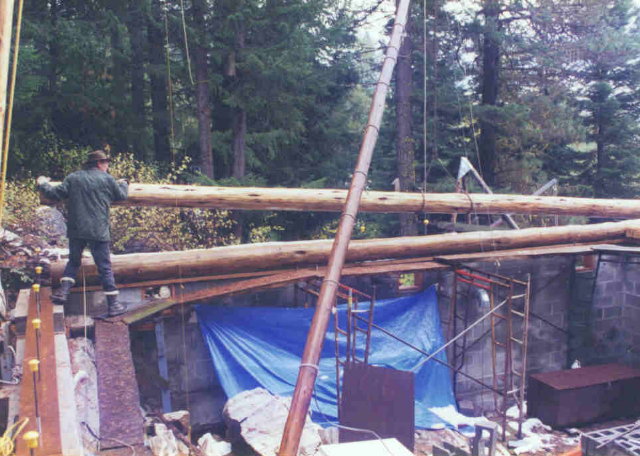
Here you see me lowering a log across a corner of the building for the same purpose of re-rigging it for another move. Each log typically took many such moves and re-riggings.
With a log choked right at its center of gravity, and the crane hook directly over the point in the wall where the center of gravity should go, it is easy to manipulate the log as it is lowered so it ends up exactly where you want it. On the last of these maneuvers, you need to choke the log so that the top of the choker is on the side of the log that you want on top. When you lift a log, it will spin so that the top of the choker is always on top so you can control the orientation easy this way.
As the PSLs and RPSLs were placed, it interfered with the boom swing. But by raising the crane it was relatively easy to raise the boom enough to clear the columns in order to swing it to wherever I wanted it.
This picture shows the placing of the Grid G purlin. It is the one on top of the columns closest to the camera. The crane could not reach far enough at this point, so I used a combination of the crane and a 12-volt winch with a block high in the tree at the right. By positioning the crane boom properly, the line between the end of the boom and the block in the tree ran directly over where I wanted the center of gravity of the purlin to go. Then using both the crane and the winch to lift the log at its center of gravity, I could control the shape of the 'V' made by the two cables so that I could lower the purlin exactly down on the tops of the three columns. I could reach the top of the column at the extreme right, behind those trees, so that end was easy to fasten. But it was a little tricky spiking the purlin into the other two columns.
The crane could reach far enough to place the Grid F purlin, so it was easier in that respect. But it was higher off the ground and the temperature was over 90 degrees the day I did it, so I think placing that purlin was the single hardest job of the entire project.
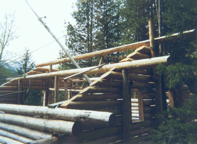
Once the Grid B and D purlins were in place, as shown here, the boom travel was pretty restricted. Then again, there wasn't much more left to lift.
When I placed the ridgepole, I had to decide on which side of it to leave the boom. I chose the left side as you can see here.
With the boom on that side, I couldn't position it directly above the Grid B2 PSL. It wasn't much of a problem because I simply ran a chain from the hook over the top of the ridgepole and the Grid B purlin, as you can see here, and from there it ran down to grab the PSL. It probably left some marks on the purlin as the chain rubbed over it, but those marks will just blend in with all the others. Here you see the PSL raised to the position where the bottom is fastened, and the top only needs to be pushed under the purlin and fastened.
I think it is not an exaggeration to say that of all the times I used the crane, which typically involved several riggings and liftings for each log, I don't think I ever did it exactly the same way twice. There was always something different about each maneuver. The logs were different sizes, they started out at different positions, I wanted to move them to different positions, and different complications arose with nearly every maneuver such as other things or parts of the rigging getting in the way. As a result, each time I used the crane I had to study the problem and imagine how to rig it and how the forces of the rigging were going to act on the load and what was going to happen once the winch or hoist began to pull. The whole process was a huge amount of fun for me.
To make sure the rigging was safe, whenever I made a change to the crane or any of its components, I would test it by connecting the hook to something immovable and then running the winch or hoist until it stopped. The winch or hoist was always the weakest part of the rigging so it would stop before anything broke. That way, if the load exceeded the capacity of the rigging, the winch or hoist would simply stop. I had a few logs that were too heavy to lift, so in these cases, I either lifted one end of the log at a time, or I put a block on the log, ran the cable through the block, and fastened the hook to something that wouldn't move.
The boom could be positioned over most of the building site but the very back wall, between the mast and the boom was a special problem. For this, and for many other special cases, I used come-alongs in conjunction with the crane. Once I got a log near the back wall with the crane, I would fasten a come-along as high up on the mast as I could with a chain. Then I would skid the log over the existing wall using that come-along and the crane hook.
If this writeup has made it seem too easy, then click here to learn about some of the problems I had and what I did about them.
©2004, 2005 Paul R. Martin, All rights reserved.