Log Home Drawings
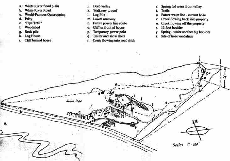
This is a bird's eye view of the property. It is sort of 3-D so you have to imagine the surface of the ground rising in the back. Most of the features drawn in are intended to be on this surface. This drawing explains many of the cryptic terms I use in my journal, so if you are wondering what I mean by, for example, "The Lower Roadway", you can find it on the drawing near the bottom marked with an 'm'. Some features are not marked, however. The "High Rock" is the high point on the cliff, 'i', behind the house. The "Hairpin Turn" is just above and to the right of the trailer, 'q', connecting the Lower Roadway, 'm', with the Upper Roadway, which is not marked with a letter either. The Walkway to roof, 'k', was temporary and used for roof construction. It is no longer there. Neither, for that matter, is the log pile, 'l'.
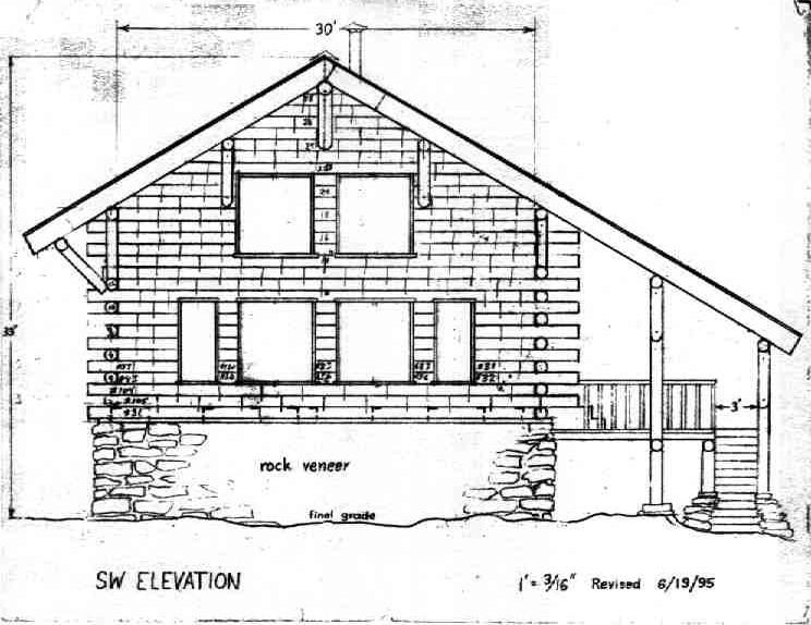
This is the front view of the house. Tom, the Structural Engineer, said that the knee braces were not required, so I didn't build them. I also didn't erase them from this drawing. Tom also had me place the spikes in the logs on closer spacing than shown on this drawing in order to prevent seismic damage. I'm glad I did. Instead of building the exterior staircase as shown on this drawing, I will flare it out at the bottom as shown in the last drawing in this set.

The floor plan has been modified slightly from this drawing. The change is that a pantry has been carved out of the space occupied by the sink in the utility room. By using an over-and-under washer/dryer, it will occupy only the footprint marked "Dry." and the sink will occupy the space marked "Wash." Another change is that the staircase to the loft will be extended two more treads toward the top of the drawing. This will make it a little less steep.

This Cross Section drawing shows many construction details and also shows the grid system from A to G in the circled letters across the top of the drawing. This might be useful in understanding what I am talking about in the Construction Journal when I, for example, refer to the Grid D purlin.
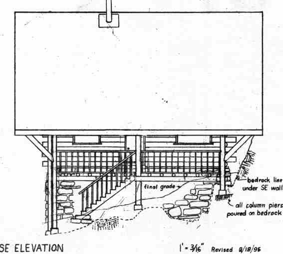
This drawing shows an edge-view of the porch deck and the front door of the house. It also shows the configuration of the bedrock under the southeast wall and going up to the cliff behind the house. That dashed line is to scale and very accurate. You can see a cross-section profile of the ledge the northeast wall is built on right behind the rightmost column in the picture. Again, the knee braces shown were not built.
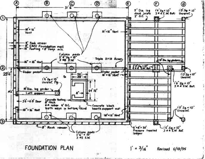
Here you see the complete grid system: the letters going from left to right, and the numbers going from top to bottom. Thus, Grid C2 is the column at the very center of the building. The sizes of the column pads were changed somewhat from those shown on this drawing. The "Concrete block hearth support wall" has not been built, and may not be built for some time. The "Concrete footing" has been poured, but the floor above will be temporarily decked over with a wood stove sitting where a masonry structure may some day be built.
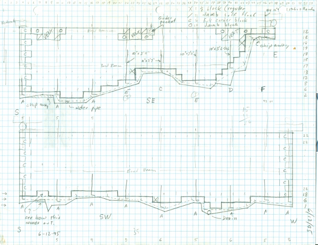
Here you see the footing and foundation elevation drawings for the Grid E and Grid 3 walls. The scale of the drawing is each square is 8 inches on a side. That means that a regular concrete block (CMU) occupies two adjacent squares. The code at the upper right (you may have to zoom in in order to read it) explains the particular type of block used. A Jamb block has a 1"x1" vertical slot in the center of an otherwise flate face on one end of the block. A corner block has one end that is completely flat. Unmarked squares contain half of a standard block. The pattern of block overlap is established by the drawing of the block orientation at the corners.
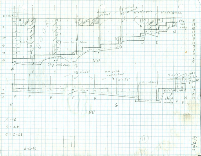
Here you see the footing and foundation elevation drawings for the Grid A and Grid 1 walls.
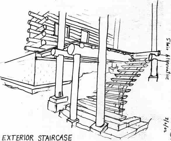
This is just a sketch representing the latest ideas on what the exterior staircase will look like. Of course, the finished staircase and deck will include handrails and balusters. The bottom few stair treads will be made of stone. They will be covered with snow in the winter, and they will stick out beyond the drip line of the roof. In the winter, all the snow piles up to the right side of this picture, so even in the deepest snow, there will be clear access to the stairs from the left side.
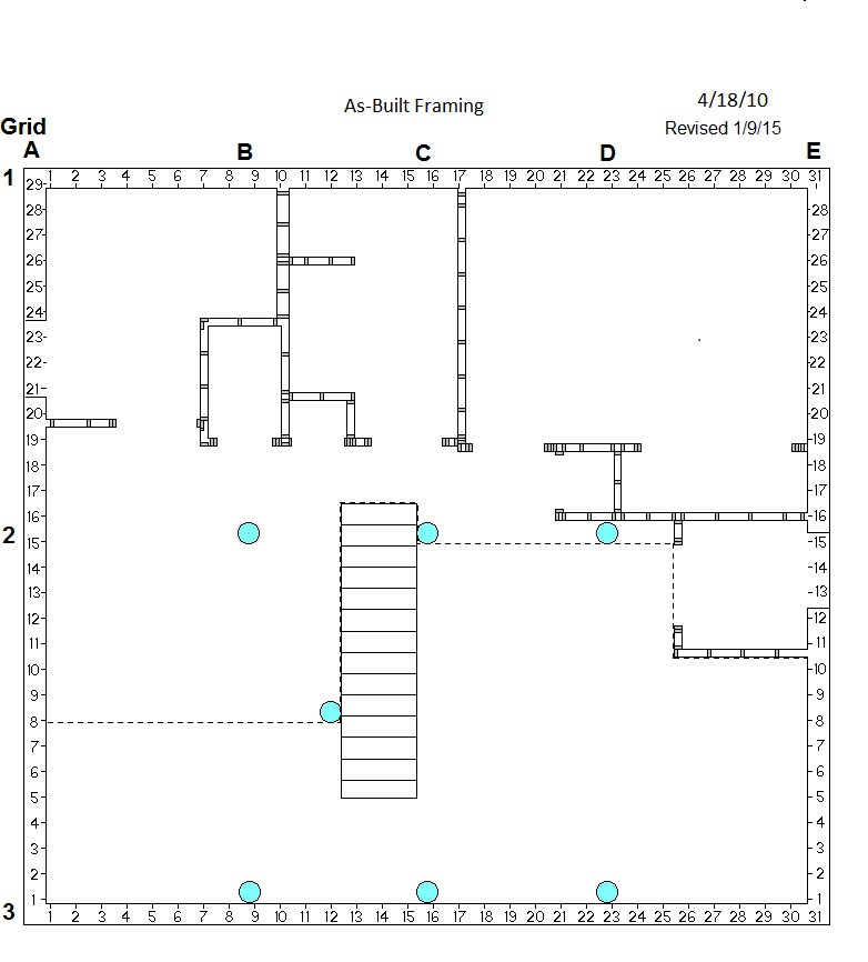
This is an accurate depiction of the first floor partition wall framing. The dashed line shows the limits of the loft floor.
©2003 Paul R. Martin, All rights reserved.